WASTEWATER
INFRAPIPE produces pipe for gravity sewer and storm water applications and low pressure potable, sewer and storm water applications. These are made in a state-of-the-art Krah machine from Europe.
Pipes are Helical wound HDPE is the ideal solution for most civil engineering pipe requirements because it has the following benefits for the asset manager, design engineer or contractor:
- Request a Quote
- Call us: 09 869 3030
- Email: [email protected]
- Office: 3 Averton Place East Tamaki Auckland 2013
Benefits
- Lighter by a factor of 14 or more.
- The best abrasion resistance.
- The best seismic resistance.
- The best chemical resistance.
- The best biological resistance.
- The best damage resistance.
- No maintenance.
- Lowest overall cost.
- Long life 100 years+.
- Completely recyclable.
- Very flexible design.
- Less manholes required.
- Short leadtime.
- Easy to install.
- Safer to work with.
- Easy to modify.
- Best for the environment.
If you are an engineer, asset manager or contractor, download this Guide to Stormwater applications which has everything you need to know.
SN Rating – Pipe Strength
The Ring Stiffness Rating (SN) of the pipe is dictated by the native soil, the cover height, the water table and the loading. Alternatives to PE are only manufactured in a couple of strengths, but the unique nature of the spiral wound product means that pipe can be designed for the exact ring stiffness required for each pipeline, each section of that pipeline or even each individual pipe. This saves money directly in the product manufacture and then in weight, freight and trench size. For those converting from concrete, Class 2 equates to SN16 and Class 4 to SN4.
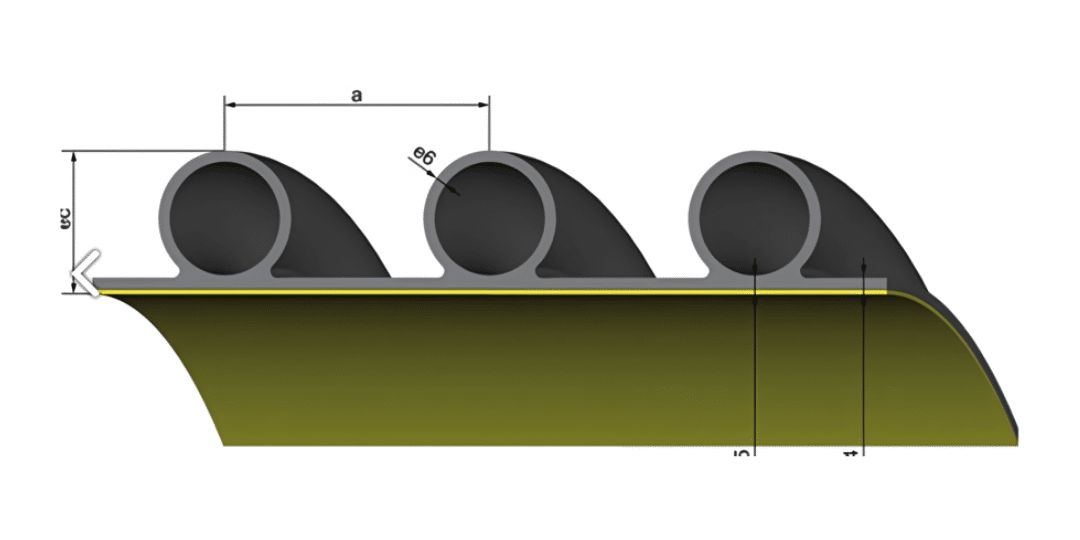
- Design software selects the most appropriate core tube size and varies the core tube spacing and thickness of inner and outer layers to achieve the required strength with the minimum material (with a significant 25% safety factor).
- As a rough guide, SN4 is for lightweight applications and SN8 or 16 for heavy traffic, depending on the cover and backfill type.
Sustainability
HDPE is completely recyclable and all excess or waste product is reprocessed by INFRAPIPE. NZS5065:2005 does not permit the use of third party recycled product but for non-civil applications INFRAPIPE uses post-consumer recyclate (PCR) in its pipes. Pipes at the end of their working life will be entirely recycled and become pipes again. INFRAPIPE observe that while concrete is theoretically recyclable, most production or site waste is buried. See this page on Sustainability for more information.
Pipe dimensions
INFRAPIPE can manufacture in a range of sizes from 450 to 3200mm in diameter as shown below. For these pipes the DN – the name – is the ID unlike some alternatives which sound 15% bigger than they actually are. The table below shows the cross-sectional area of the pipe – and its equivalent in smaller pipes (shown by their ID). For use where burial is required, the cross-sectional area with 25% burial is also shown. Weight and OD are shown for the typical sizes for light duty and heavy duty applications; the OD is used for trench dimension calculations.
DN(ID) | Cross-sec | Equivalent to | 25% burial | SN4 | SN16 | |||
2 of ID | 3 of ID | OD | Weight | OD | Weight | |||
450 | 158,963 | 300 | 250 | 127,869 | 528 | 78 | 542 | 90 |
525 | 216,366 | 375 | 300 | 174,045 | 603 | 91 | 621 | 141 |
600 | 282,600 | 375 | 300 | 227,323 | 678 | 103 | 720 | 175 |
700 | 384,650 | 450 | 375 | 309,412 | 792 | 142 | 842 | 212 |
800 | 502,400 | 525 | 450 | 404,131 | 892 | 187 | 962 | 263 |
900 | 635,850 | 600 | 525 | 511,478 | 1020 | 257 | 1096 | 329 |
1000 | 785,000 | 700 | 600 | 631,454 | 1120 | 284 | 1196 | 390 |
1100 | 949,850 | 700 | 600 | 764,059 | 1242 | 325 | 1332 | 428 |
1200 | 1,130,400 | 800 | 700 | 909,294 | 1222 | 325 | 1464 | 463 |
1350 | 1,430,663 | 900 | 700 | 1,150,825 | 1546 | 490 | 1596 | 735 |
1500 | 1,766,250 | 1000 | 800 | 1,420,772 | 1696 | 541 | 1776 | 889 |
1600 | 2,009,600 | 1100 | 900 | 1,616,522 | 1796 | 576 | 1878 | 943 |
1800 | 2,543,400 | 1200 | 1000 | 2,045,911 | 2032 | 703 | 2068 | 1609 |
2000 | 3,140,000 | 1350 | 1200 | 2,525,816 | 2232 | 978 | 2308 | 1878 |
2300 | 4,152,650 | 1600 | 1350 | 3,340,392 | 2572 | 1172 | 2634 | 2796 |
2500 | 4,906,250 | 1800 | 1500 | 3,946,588 | 2778 | 1454 | 2842 | 3395 |
3200 | 8,038,400 | 2000 | 1800 | 6,466,089 | 3500 | 2981 | Ask | |
Standards
INFRAPIPE is accredited to ISO 9001:2015 and the pipe is certified to ISO Type 5 5065:2005, these certificates can be provided on request or found on the INFRAPIPE website. Producer Statements and Certificates of Conformity can be issued by INFRAPIPE on request. Overall testing is in accordance with ISO 5065:2005 and raw material used is tested for Melt Mass-Flow Rate (MFR) in accordance with ISO 1133-1:2022 Plastics – Determination of the melt mass-flow rate and melt volume-flow rate of thermoplastics. All resins used are certified to AS/NZS 4131:2010 and batch certificates are retained.
- Installation Instructions are in accordance with AS/NZS 2566.1:1998 Buried Flexible Pipelines: Structural design and AS/NZS 2566.2:2002 Buried flexible pipelines – Installation. Manufacture of the product is designed to DIN16961, EN13476, ASTM F894 and ISO 9969.
Bends
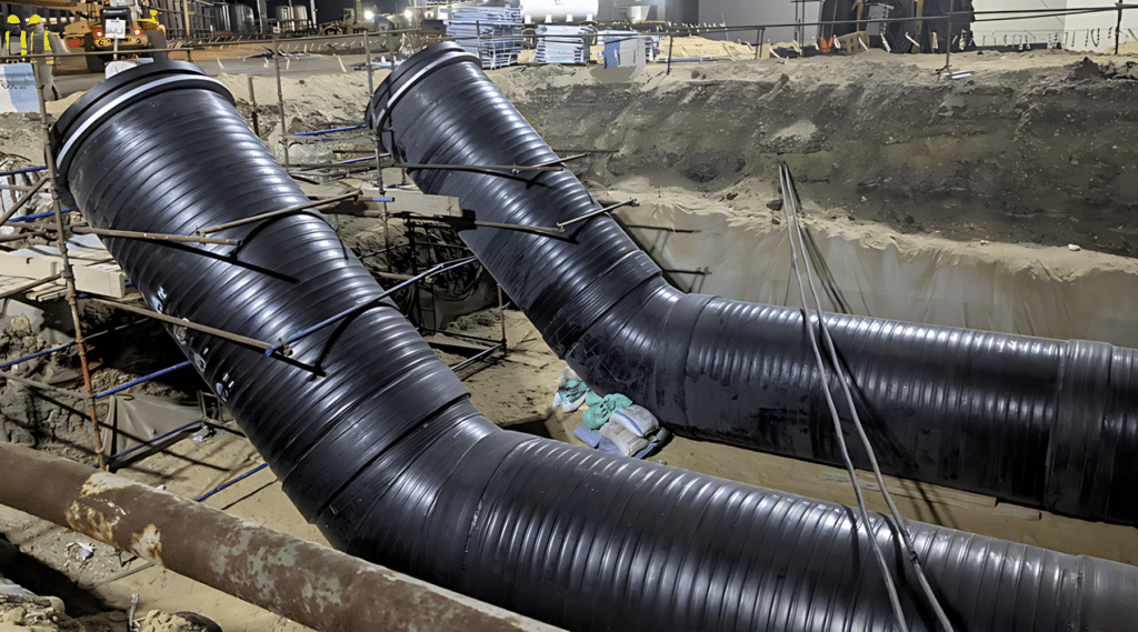
No more expensive manholes for every change of direction! INFRAPIPE can be fabricated into any angle. Now the pipeline suits the site not the site being designed around the pipes and manholes.
- The example below is from the worlds largest water treatment plant, completed in 2023 in Egypt. It also proves that HDPE pipes are the best option when faced with the poorest soils which can barely support a human:
Joining the pipe
INFRAPIPE has an effective length of 5800mm (pipe length 6000mm).
Shorter lengths can be produced which means there is no waste and the asset owner is not charged for a length of pipe which then has to be cut, and the offcut disposed of. Pipes can be joined in factory for a delivered length of 11.8m or longer.
Whilst joins are normally located at full pipe lengths (effective length is 5800mm) the presence of bends and structures can require them to be located at shorter lengths; INFRAPIPE will calculate this.
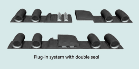
There are two types of joins used for INFRAPIPE; Double Rubber Ring Joint (RRJ) is the standard join which is conducted by contractor staff onsite. Each join takes approximately ten-twenty minutes in good conditions (dependant on pipe size).
- Electro Fusion (EF) Welds are performed onsite by INFRAPIPE specialist personnel or by contractor personnel who have been trained by INFRAPIPE. This is a much more sophisticated process than the small EF couplers used – see more detail on EF welding process. EF welds take approximately one hour each, depending on pipe size, during which time the next pipe can be laid in the trench ready for insertion and joining.
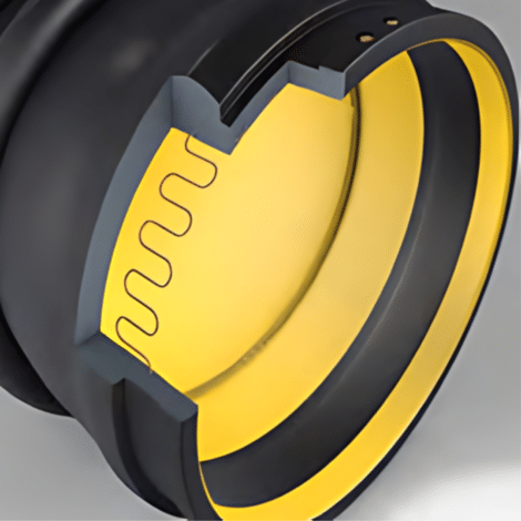
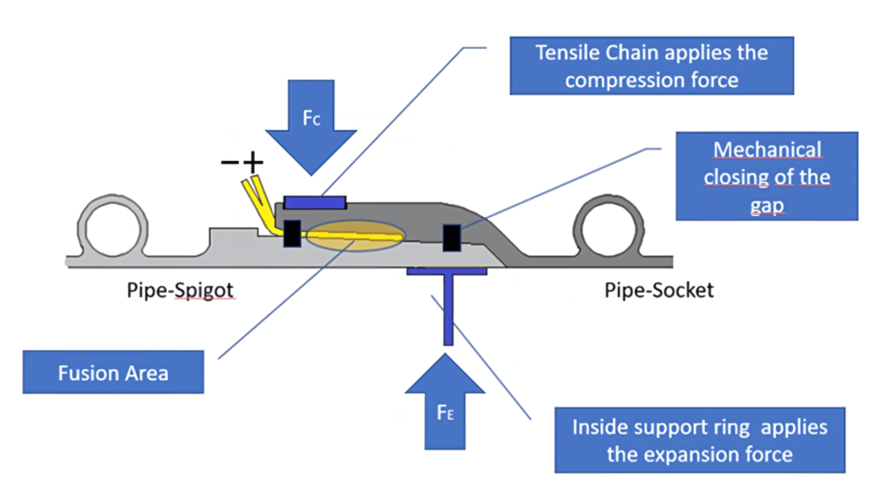
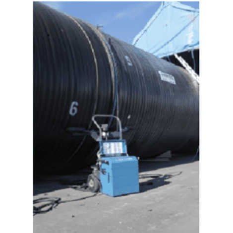
EF welds are essential with significant grades or where the pipe is pressurized and are preferred by some asset owners for all waste applications as there is no possibility of infiltration.
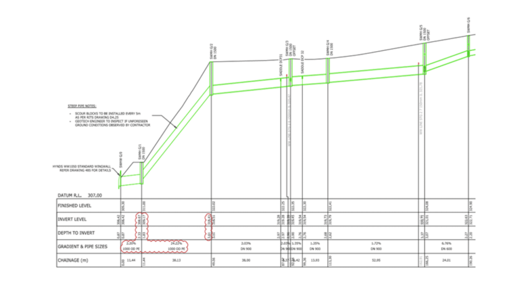
- The gradient at this project in Wharenui Rise required EF joins because of the 22% fall. Once welded nearby, it then took 2 minutes 47 seconds for three diggers to position the entire 51m section next to the trench. See this video of the installation
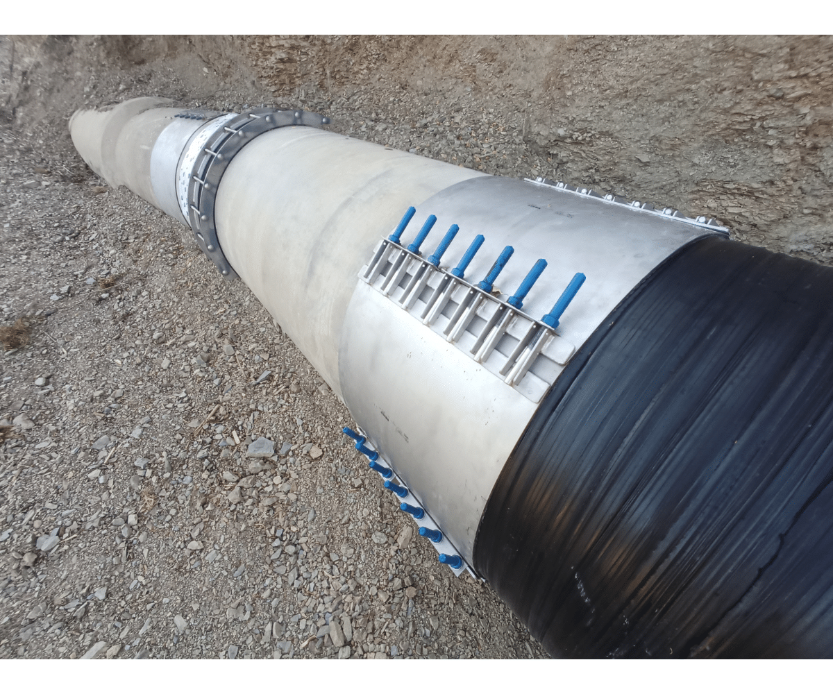
Can INFRAPIPE join to existing concrete?
Easily with a FITTING like this:
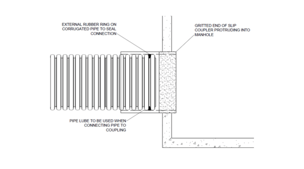
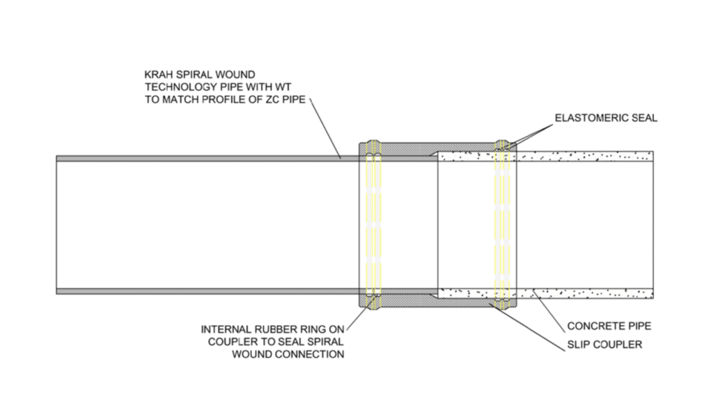
- This Manhole ‘starter’ is a very effective, reliable and easy to fit means of joining HDPE pipes to concrete structures. For joining HDPE pipe to concrete pipes INFRAPIPE uses a slip coupler:
Solid Wall Alternatives
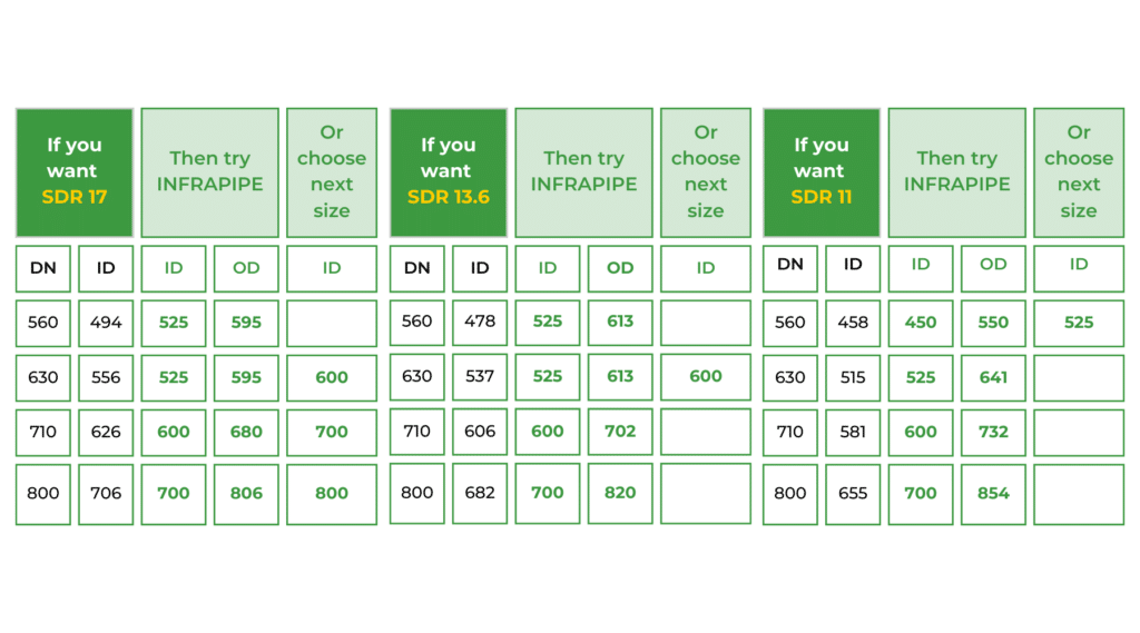
The KRAH Technology can also create solid wall pipe which can be much more economical than traditional inline extrusion (which has large setup costs) for shorter runs of larger diameters, or more extreme wall thicknesses. Whilst the table below shows the most common SDRs (Standard Dimension Ratios – which dictate the wall thickness for a given pressure rating), INFRAPIPE can achieve any SDR.
Emergency repairs
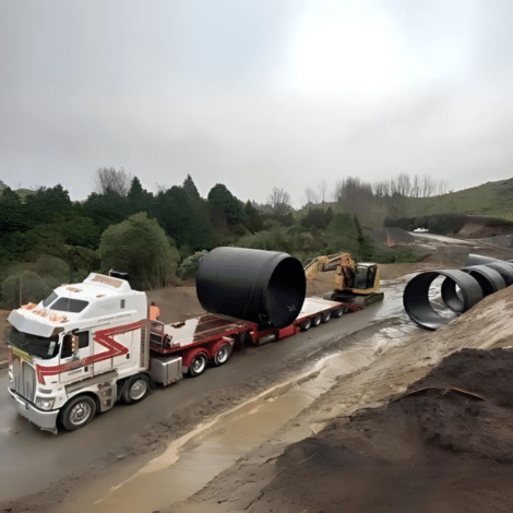
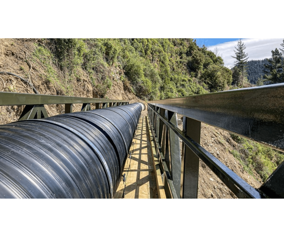
There is no tooling setup or curing time for INFRAPIPE – pipe can be made and used immediately. When Nelson main water supply was washed away in Sep 22, INFRAPIPE despatched a truck load of replacement three days later.
Spiral HDPE is the pipe of choice in the earthquake prone Philippines for supplying the hundreds of hydro electric schemes as it can be quickly and easily repaired after a seismic event. The pipe itself Is not damaged by the earthquake, but then the hill side falls away afterwards!
Trench Design & Cover
INFRAPIPE will advise on the specific trench design and cover height when supplied with Geotech and water table data, to minimize installation cost. The general details of trench and cover requirements are below, and available in This Handling & Installation Guide.
Minimum Cover & Embedment Zone Geometry
This section is about the minimum cover, embedment zone geometry and requirements and is written in accordance with Section 4 of AS/NZS 2566.2.
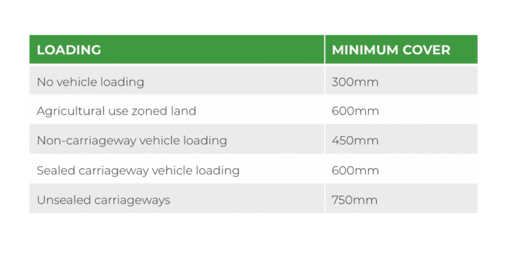
Minimum Cover
The minimum pipeline cover is specified to:
- Ensure surcharge loadings are, e.g., construction loading or design loading, are not concentrated and are distributed over an appropriate area.
- It is important to provide sufficient cover clearance to overlying layers that require heavy mechanical compaction, e.g., road sub-bases.
- Ensure the pipe embedment or side support is appropriate in regard to the proposed land use and any foresteable lowering of finished surface levels.
Minimum cover heights on pipes are available in Table 4.1 from AS/NZS 2566.2:2002, which states:
Embedment Zone Geometry
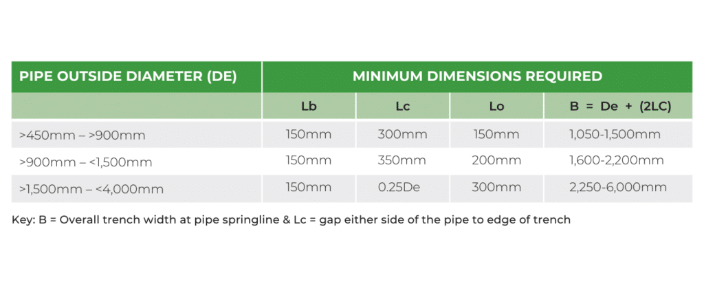
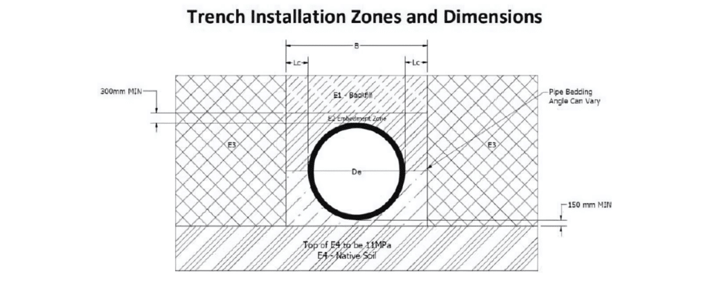
The minimum width of a trench, measured at the springline, shall comply with Table 4.2 from AS/NZS 2566.2:2002 and shall be sufficient for:
- The placement and compaction of the designated embedment materials, particularly below the pipeline springline in the haunching area. It is important that the material is compacted to the specified relative compaction rate.
- Connection and inspection of joints.
INFRAPIPE™ can make design consideration for narrower trenches, but this needs to be made known as a requirement during the structural design stage. The trench width above the embedment zone shall be determined by considering the stability of the trench wall material and any trench support that is required for installation.
The minimum trench zone dimensions are displayed in Table 4.2 from AS/NZS 2566.2:2002, see below:
Embedment (E2) Zone Materials
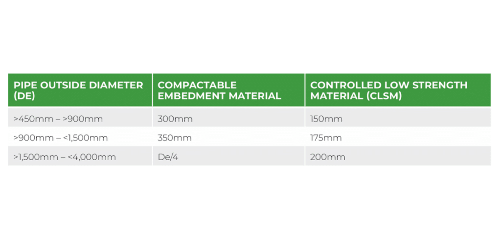
For the minimum embedment spacing between parallel pipelines refer to table 5.1 from AS/ NZS2566.2:2002 (below):
MATERIALS AND COMPACTION REQUIREMENTS
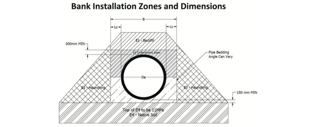
This section is about the materials used for embedment and compaction rates required to be used during installation and is written in accordance with Section 5 of AS/NZS 2566.2:2002. The trench drawing below is to be used to reference pipe zones E1, E2, E3 & E4.
Embedment (E2) Zone Materials
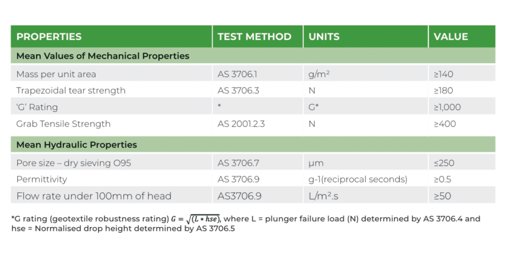
It is important to identify if there is a possibility of migration of fines between the native soil and the embedment zone material, a geotextile filter fabric should be considered, as long as it complies with Appendix J of AS/NZS2566.2:2002. The geotextile filter fabric shall be a non-woven fabric made from filaments of synthetic fibres, which meets the requirements specified in Table J1.
Table J1: Specification for Geotextile Filter Fabric
Native soils, particularly cohesionless soils with gradings no finer than those specified in Table G1, may be suitable where approved by the engineer and/or the manufacturer. It is important to avoid sands that are prone to ‘bulk’ when moist. Where they are used, ensure that the required density will be achieved.
Table G1: Cohesionless Native Soils Acceptable for Embedment Material
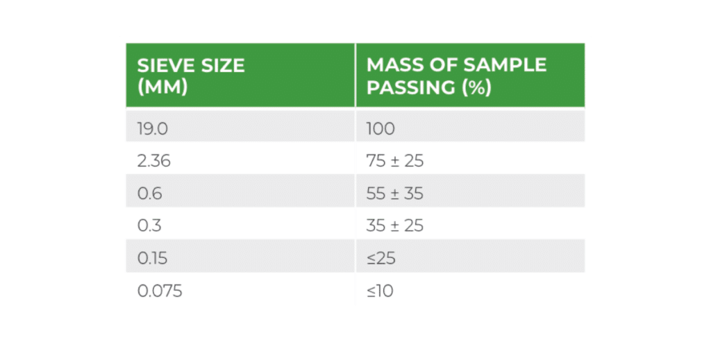
Imported cohesionless embedment material with gradings specified in Table G2 and Table G3 will facilitate the achievement of the soil moduli given in Section 3 of AS/NZS 2566.1:1998: Buried flexible pipelines – Structural design.
Note: Compaction equipment will be required for all embedment materials except for coarse aggregates.
Table G2: Processes aggregates acceptable for embedment materials
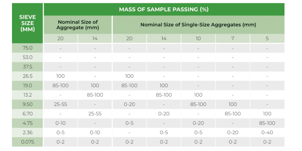
Table G3: Other materials acceptable for embedment materials
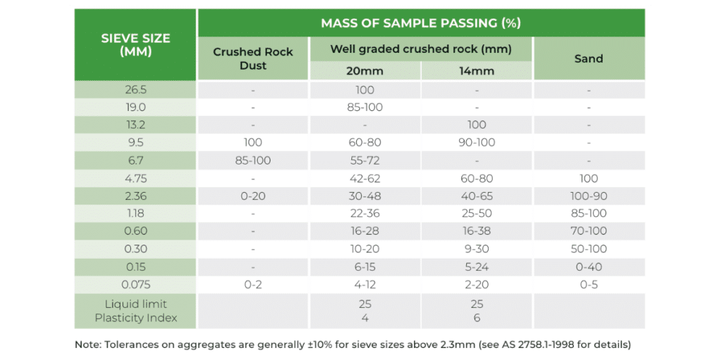
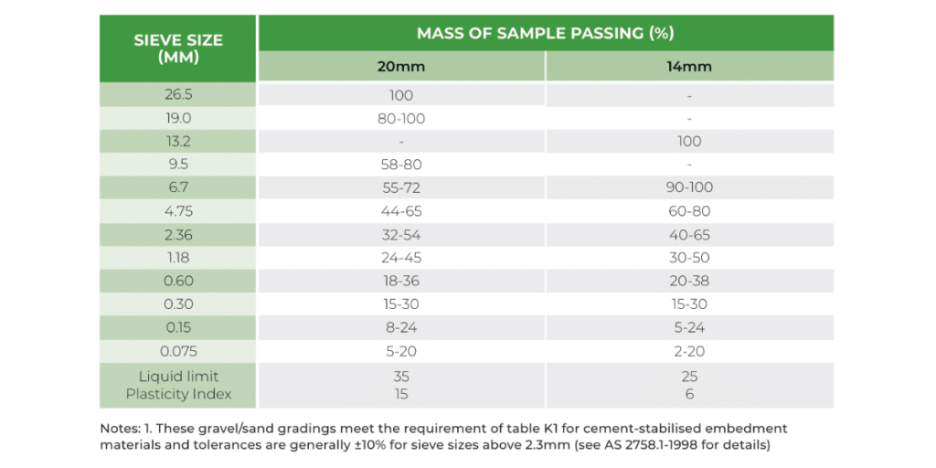
Table G4 should be used where gravel/sand gradings meeting the requirements of Table H1 for cement-stabilized embedment material are required (the gravel gradings in Table G2 and Table G3 do not meet the criteria).
Table G4: Embedment material suitable for cement stabilisation
