Technology
High-performance plastic pipe production technology
INFRAPIPE uses three different types of pipe making machinery:
- Helical wound KRAH pipe for pipes with an ID 375-3200
- Solid wall inline extrusion for pressure pipe with OD 20-355
- Twinwall inline extrusion for gravity pipe with ID 100-1000
- Request a Quote
- Call us: 09 869 3030
- Email: [email protected]
- Office: 3 Averton Place East Tamaki Auckland 2013
KRAH Helical (Spiral) Wound
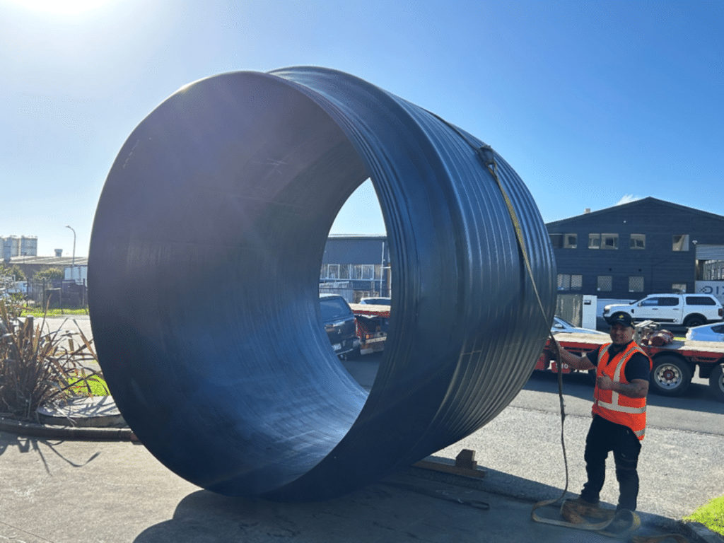
To make a Krah spiral-wound pipe, the resin and core tube (s) are extruded onto a rotating mandrel:
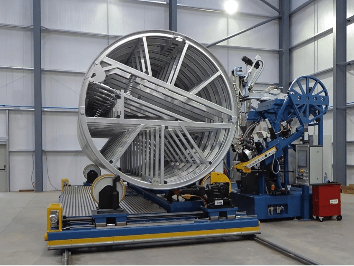
The mandrel is 6m in length allowing for individual pipes of 6m or an effective length of 5800mm once pipes are joined (see below for more details on joining the pipes). Shorter pipes can be made if needed and pipes can be joined in the factory to give a delivered length of 11.8m or longer.
- Mandrels held are 375, 450, 525, 600, 700, 800, 900, 1000, 1100, 1200, 1350, 1500, 1600, 1800, 2000, 2300, 2500, 3200 and by arrangement 1400 and 3500.
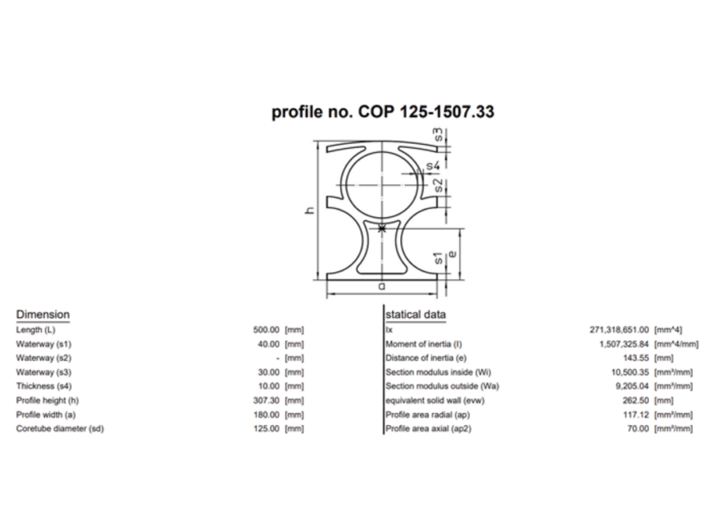
The profile type produces the required SN rating:
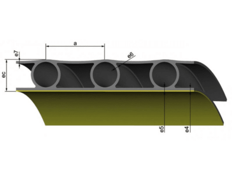
There are numerous different profile types, these are the most common ones for INFRAPIPE:
- PR is the basic inner layer with one core tube layer
- CPR is a PR profile but covered with an external layer
- SW is a solid wall profile with no core tube
Standard pipes and bends are PR, CPR is used for tanks and for relining and SW is used for solid wall pipe or for manholes and connections.
Solid Wall Inline Extrusion
The act of producing the humble pipe that brought water to your tap is a complex one:
- Two extruders are fed raw material by two Gravimetric dosimeters
- The larger of these extruders supplies resin for the body of the pipe
- The smaller one adds a coloured jacket or stripe to the pipe if required
- The liquid resin from both extruders is fed into a die which shapes it to create a circular output
- An inner mandrel in the die creates the circular shape on the inner of the pipe
- The pipe then feeds from the die into a vacuum tank
- This vacuum tank then preserves the circular shape of the pipe as it begins to cool
- From the vacuum tank the pipe continues to a water spray tank
- The pipe continues to cool
- The pipe goes to the tractor unit which pulls/pushes it down the line
- The pipe goes past a printer which adds batch data to identify the pipe
- The pipe goes into a cutter and is cut to length
- The pipe is then received by a tipping table, for lengths or –
- The pipe is coiled on a coiler
To change the pipe being made, the following must be changed:
- Potentially the resin in one or both extruders
- The die and all its connections
- The mandrel
- The tooling for the pipe output
- The apertures on the six stations above, both sides
- The roller heights to support the pipe along 40-60metres of machine
- The tractor unit dimensions
- The printer location
- The printer settings
- The cutter settings
- The tipping table or coiler settings
Twinwall Inline Extrusion
A twinwall line is simpler than a solid wall line, but just as time consuming for a tool change:
- Two extruders are fed raw material by two Gravimetric dosimeters
- The larger extruder feeds to the outer part of the die
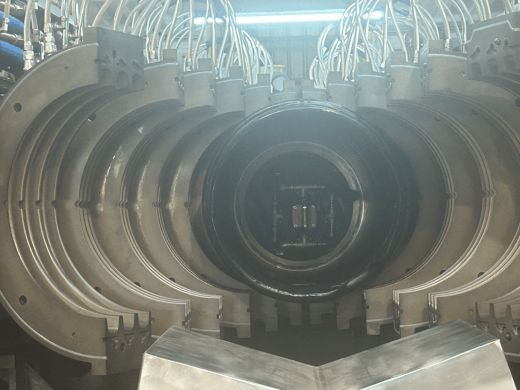
- From the end of the die the resin is sucked into cavities in rotating blocks
- These cavities shape the corrugations which give the pipe its strength
- The vacuum in these blocks continues until the pipe has been welded together
- The resin from the smaller extruder passes through the interior of the die
- It passes over a mandrel to shape it and then emerges between the blocks
- This inner layer welds to the outer layer whilst this is still held in the blocks by vacuum
- The vacuum ceases as the blocks part
- The blocks continue to rotate around the corrugator to return to the die
- The pipe is now clear of the mandrel and corrugator
- It enters a cooling tank
- From the cooling tank it proceeds to the tractor unit
- The tractor unit propels it to the printer
- After printing it enters the cutter
- The cutter cuts at the socket and again shortly after to form the spigot
- The pipe is then received by a tipping table, for lengths or –
- The pipe is coiled on a coiler
To change the pipe being made, the following must be changed:
- Potentially the resin in one or both extruders
- The die and all its connections
- The mandrel
- The 38 pairs of blocks in the corrugator
- The apertures on the three stations above, both sides
- The roller heights to support the pipe along 20 metres of machine
- The tractor unit dimensions
- The printer location
- The printer settings
- The cutter settings
- The tipping table or coiler settings
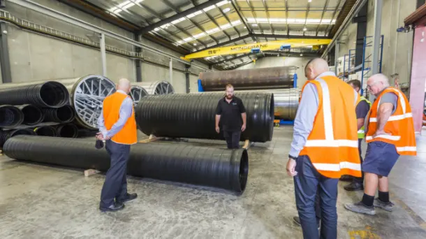
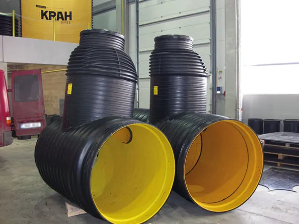
Due to the engineered structural technology, Infrapipe™ Spiral is easily fabricated in many ways so we can look at the overall project and see how Infrapipe™ Spiral can be used to reduce manholes sizes, limit excavation, and overall improve the system. Infrapipe™ Spiral can do this by:
- Prefabricated manholes.
- Smaller manhole risers or ‘Chimney’ risers.
- Plug & play tanks, manholes and bends.
- Manufactured with longer length or pre-welded strings of pipe.
All these options provide benefits to all parties involved by reducing installation time, onsite health & safety risks, reducing cost and minimising the environmental impact of large excavations.
Advantages
Advantages of Infrapipes
Infrapipe™ Spiral is typically used in drainage, stormwater and wastewater applications around the country and is often the preferred option due to its many advantages:
- 100-year design-life.
- Manufactured from materials that are 100% recyclable.
- Light weight so easy to handle with smaller equipment.
- High abrasion resistance.
- Extremely high chemical resistance even to HS2 (hydrogen sulphide) attack.
- Low Manning’s coefficient of friction due to smooth internal bore.
- Easily fabricated into pipeline componentry like tanks, manholes, bends, reducers, etc.
- Low waste due to being manufactured to the chainage required, not just 6m lengths.
Applications
Made in NZ using the latest European technology
Infrapipe™ Spiral is typically used in drainage, stormwater and wastewater applications around the country. Typical uses include:
- Stormwater Pipelines
- Wastewater Pipelines and Outfalls
- Raw Water Lines
- Culverts
- Tanks
- Manholes
Jointing Technologies
Made in NZ using the latest European technology
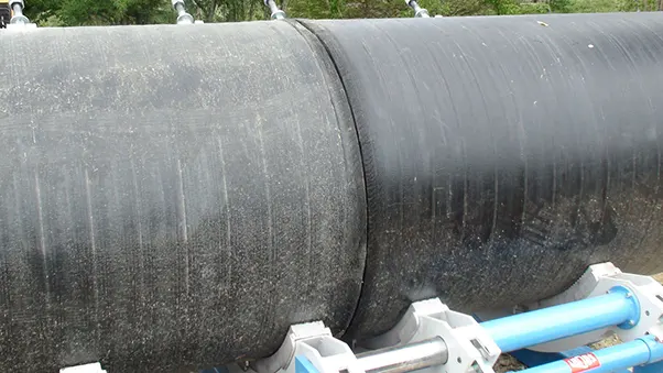
Infrapipe™ Spiral is extremely adaptable to how it can be connected to itself and other products with its large range of jointing types. Each project can have the jointing types designed to suit any specific requirements or multiple options can be used.
All jointing types have a specific methodology for leak testing during the installation process, not at the end or between structures. Jointing types include:
- Socket/Single or Double Rubber Ring Spigot
- Stub Flange and Backing Ring
- Electro-fusion Socket/Spigot
- Extrusion Welded
- Butt Welded

